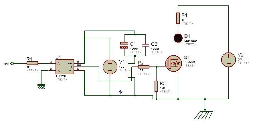
Ir2110 Mosfet Driver Circuit Diagram
What is the purpose of 2222N transistor in MOSFET driver circuit using. It is simpler to use the gate driver shown in the diagram that half an IR2110. A visitor from Denizli viewed 'Tahmid's blog: Using the highlow side driver IR2110 explanation and plenty of examp circuits' 0 secs ago A visitor from Kolkata. Anonymous March 18, 2013 at 9:27 PM hi tahmid can i use single ir2110 and single sg3525 to drive h-bridge ' 4 mosfet' and i want full circuit diagram of drive. HIGH AND LOW SIDE DRIVER Product Summary VOFFSET (IR2110) 500V max. (IR2113) 600V max. IO+/- 2A / 2A VOUT 10 - 20V ton/off (typ.) 120 & 94 ns Delay Matching (IR2110) 10 ns max. (IR2113) 20ns max. Www.irf.com 1 Description The IR2110/IR2113 are high voltage, high speed power MOSFET and IGBT drivers with independent high and low side referenced.

This is my first post here, i need help on my final year project to make a grid connected inverter. How To Install Plugins For Imagej. For the full bridge inverter circuit i planned to use IRF2807 (75V Vds, 82A Ids) and Two IR2110 for the driver. I never use IR2110 before and failed many time when i want to make a H-Bridge for DC motor last year. Hopefully after asking you guys i can get enlightenment for my final year project. I planned to design the circuit based on this sample project that i get from another website: i have some question about the schematic since the specification is quiet different.
My DC input voltage is 34V (2 series solar panel), The power rating is about 100Watt so the MOSFET should able to drain about 10A max current. Creole Fires Kat Martin Pdf Free. The output of the inverter will be connected to 18V - 220V step up transformer. My controller will use hysteresis current control method so the switching frequency is not fixed and varied up to 100kHz.
And i want to isolate (different ground) between my micro controller and power circuit. How can i use the optocoupler to isolate it? Is there any optically isolated buffer since i planned to use buffer (micro controller (ATmega 8535, 16MHz ->Buffer IC ->Optocoupler ->IR2110) Based on my specification, is there any component that i should change? I read before to change the diode to the fast recovery one, and change the resistor value. I will appreciate any suggestion or critics, thanks in advance. If you have to isolate your ground, I would recommend you to use isolation transformer instead of optocoupler. In this, you will no longer need to use high-side capable driver ICs, you will instead use a small gate drive transformer, buffered by the totem-poles.
The transformer is very easy to wind, use small toroid core, about 10mm outer diameter or even slightly smaller. Make sure that it will not saturate. See the schematic below. Just make sure that you follow the polarities, you already know that of course. Feel free to ask if you have further questions. If you have to isolate your ground, I would recommend you to use isolation transformer instead of optocoupler.